Daniel Quayle patents
1883

A series of metal bars E or their equivalents are fixed to the bottom
rail of the lower, or the top rail of the upper, sash. When the sash is
closed they are concealed in the vertical pieces F, but when it is
opened they are brought into position opposite the opening, so as to
form an obstruction to prevent people from accidentally falling out, or
from effecting an entrance through the open window. The obstructing
bars may either be each separately secured to the sash, or they may be
fixed.
1890
 SPONGE-HOLDER
SPECIFICATION forming part of Letters Patent No. 430,434, dated June 17, 1890.
Application filed October 18, 1889 - Serial No. 327,410. (No model.) Patented in England August 1, 1888, No. 11,149.
To all whom it may concern:
Be it known that
I, DANIEL F. W. QUAYLE, of Bridge House, Castletown, Isle of Man, Great
Britain, have invented a new and useful improvement in Sponge-Holders,
(for which I have obtained a patent in Great Britain, No. 11,119, dated
August 1,1888); and I do hereby declare that the following is a full,
clear, and exact description of the same.
My invention is
designed especially for travelers' use; and it consists of a holder or
receptacle adapted to receive a sponge and other articles, if desired,
and provided with a locking device by which the articles contained may
be kept strictly for private use.
Another feature
of my invention is making the holder collapsible, so that it maybe
folded into small compass for packing within a trunk or satchel. A
device intended to hold a sponge must be formed to permit free access
of air thereto and the free escape of moisture, so that the sponge may
become dry and pure, and for this purpose the device herein shown is
made of open-work.
I have shown in
the accompanying drawings several forms of holders embodying all the
essential features referred to above.
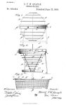
Figure l
represents a side view of a spherical form of collapsible holder. Fig.
2 is a vertical section of a modification. Fig. 3 is a sectional view
of another modification.
Referring more
particularly to Fig. 1, the holder consists of two central rings or
hoops A, of non-oxidizable metal, hinged together, and each having in
connection with it a series of smaller hoops A, the connection being
made by cords, bands, chains, or like flexible mediums, as at B. These
hoops are of successively smaller size, so that the general shape of
the holder when distended and in use is spherical; but it will be
understood that the principal of my invention may be embodied in
holders of other shapes, as will be hereinafter shown.
The hinging of
the two main hoops A allows the holder to be opened for the reception
of the sponge, and for the purpose of preventing use of the contained
article by unauthorized persons a lock C is provided, which holds the
two parts of the receptacle together and prevents the withdrawal of the
sponge therefrom. Besides holding the sponge, the receptacle may be
provided with suitable rests for receiving other articles - such as a
tooth brush - and such rests are shown at Fig. 1, consisting of lugs or
projections between which the article may be clipped when the holder is
closed, and from which it may be released upon opening the receptacle.
While the sponge may be securely inclosed by the receptacle, it will be
noticed that at all times the air has free access thereto and the
moisture is free to escape by reason of the openwork structure of the
holder. Besides these desirable characteristics, another important
quality lies in the collapsible feature of the receptacle, for when the
sponge is removed the whole device maybe folded into very small
compass, the outside hoops lying within the main hoops, this being
desirable for travelers to enable them to place the article within a
satchel or the like; or, if desired, the sponge may be retained in the
receptacle, and by applying pressure the whole device can be rendered
small enough to be placed in any convenient corner of the smoker
satchel.
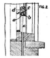
Fig. 2
illustrates a departure from the general shape of the device shown in
Fig. 1, the form here being conical. The hoops A are secured to the
hoop A by the chains B, and the hoop A constitutes the top and mouth of
the receptacle, having hinged thereto a cover D, consisting of
wire-netting secured to band A. This band is hinged at b to the band A
and provided with a lock at C. Within this receptacle there is a
supplemental receptacle or compartment (1, located directly beneath the
cover D and provided with a flap or door). This compartment is intended
to receive a tooth-brush or the like and preserve it against use by
unauthorized persons. E are hinged feet or supports capable of being
folded against the hoops when the receptacle is collapsed. F is a tray
for catching drips, which maybe attached to the bottom ring of the
receptacle. These parts, while shown with this modification, are
applicable to the form shown in Fig. 1, as represented in dotted lines.
Fig. 3 shows a further modification, the two-part top or cover being
marked A-A hinged together and under tension of spring e, which
automatically opens the receptacle, as shown by full lines, when the
parts are unlocked at 1. A supplemental receptacle 1, having a cover,
is also provided in this form. The body of the holder in this instance
consists of the net-work bag A, made of strings, wire, chains, or other
material which will admit of being wrapped about the rings A-A when
closed.
The device may be suspended in any suitable manner.
What I claim is
1. A
sponge-holder consisting of a ring or hoop, a body portion depending
therefrom, said portion being collapsible and formed of open-work to
permit the escape of moisture, and a hinged covering portion,
substantially as described.
2. In a
sponge-holder, the combination of a body portion of collapsible
open-work, adapted to receive the sponge, a hinged covering portion,
and supplemental means adapted to receive other articles, substantially
as described.
3. In
combination, the hoop or ring having connected thereto the open-work
collapsible body consisting of a series of hoops joined by flexible
connection, and a covering portion, substantially as described.
4. In
combination, the hoop or ring having connected thereto the open-work
collapsible body portion consisting of a series of hoops joined
byfiexible connections, and a covering portion consisting of the hoop
or ring with open-work connected therewith, substantially as described.
5. In
combination with the receptacle consisting of the open-work body
portion and the open-work cover, the two parts being hinged together,
and the lock 0, whereby the escape of moisture is permitted by
evaporation and drainage while the article is locked from unauthorized
persons, substantially as described.
6. In combination, the collapsible receptacle and the supports hinged thereto, substantially as described.
7. In
combination, the collapsible receptacle and the tray F, positioned
below the same and secured thereto, substantially as described.
In testimony whereof I have signed my name to this specification in the presence of two subscribing witnesses.
DANIEL F. W. QUAYLE.
Witnesses:
WILLIAM QUAYLE, SAMUEL LINDOW BURNS
Back
to St George-in-the-East Clergy 1860

 SPONGE-HOLDER